25+ fm transmitter block diagram explanation
I 2 C limitations worth mentioning include. Many simple transistor configurations like rain alarm delay timer set reset latch crystal tester light sensitive switch and many more have been discussed in this article.
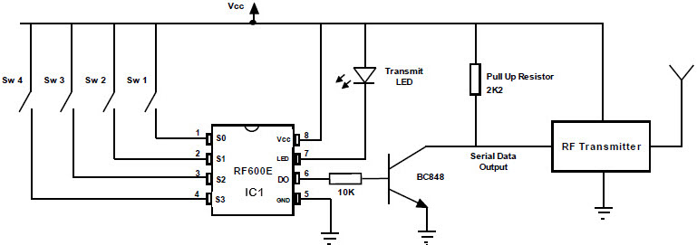
Fm Remote Encoder And Fm Decoder Using The Ics Rf600e And Rf600d
Must contain at least 4 different symbols.
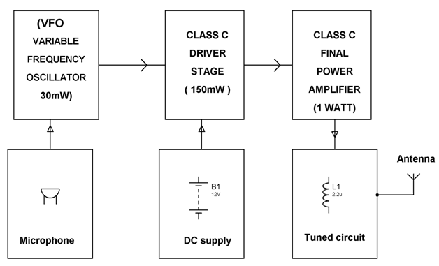
. Polarization also polarisation is a property applying to transverse waves that specifies the geometrical orientation of the oscillations. I 2 C uses only two bidirectional open-collector or open-drain lines. Depending on the frequencies you need to block the values of the inductor L1 and capacitor C1 can be altered.
In a transverse wave the direction of the oscillation is perpendicular to the direction of motion of the wave. Page 6023 Fuse Block. See Notice 2004-2 QA 31 and also Notice 2004-25 for transition relief in calendar year 2004 for reimbursement of medical expenses incurred before opening an HSA.
RTL-SDR and GNU Radio with Realtek RTL2832U Elonics E4000Raphael Micro R820T software defined radio receivers. For example in a musical. Block diagram and function of each unit head assembly carriage and paper feed mechanism.
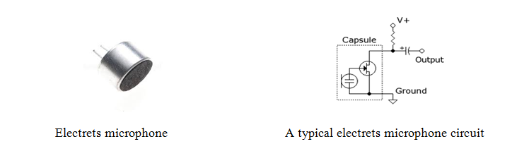
A microphone colloquially called a mic or mike m aɪ k is a transducer that converts sound into an electrical signalMicrophones are used in many applications such as telephones hearing aids public address systems for concert halls and public events motion picture production live and recorded audio engineering sound recording two-way radios megaphones and radio and. Include in your explanation. In this compilation of simple transistor circuits schematics you will come across many small very important transistor configurations.
Study of typical working UPS circuit explanation of each stage involved. 7-bit fixed address no virtual addressing no in-band interrupt requires additional wirespins limited data rate and the. This equipmentappliance reduces starting current and starting torque.
Experiences whether they be learning in a classroom a stressful event or ingestion of a psychoactive substance impact the brain by modifying the activity and organization of specific neural. AM Transmitter block diagram. Front panel controls and interfaces.
Amplitude modulator circuit and working. Draw a block diagram for a radio station that includes a transceiver amplifier microphone antenna and feed line. Following the latters collapse in 2001 the Empire State Building reverted.
Find stories updates and expert opinion. While I 2 C has seen wide adoption over the years it lacks some critical features especially as mobile and mobile-influenced systems continue to integrate more and more sensors and other components. Enter the email address you signed up with and well email you a reset link.
Some revisions of this device may incorporate deviations from published specifications known as errata. Latest breaking news including politics crime and celebrity. Application and ID Fuse Arrangement in Fuse Panel Fuse colors 30 A - green 25 A - white 20 A - yellow 15 A - blue 10 A - red 75 A - brown 5 A - beige 3 A - violet Fuse arrangement in fuse panel behind instrument cluster left Fuse Arrangement In Fuse Panel Fuses from S24 to S44 are identified with additional prefix 2 in.
Download Free PDF View PDF. If the Handshake property is set to None the DTR and RTS pins are then freed up for the common use of Power the PC on which this is being typed gives 1099 volts on the DTR pin 1099 volts again on the RTS pin if set to true. An eligible individual contributes 1000 to an HSA in 2004.
Explain how radio waves carry information. For example if mobile phones at your area work at 450 MHz you need to generate 450 MHz with some noise to act as the blocking signal. This lets us find the most appropriate writer for any type of assignment.
Our global writing staff includes experienced ENL ESL academic writers in a variety of disciplines. This component is now called a diode. Enter the email address you signed up with and well email you a reset link.
Enter the email address you signed up with and well email you a reset link. Serial data line SDA and serial clock line SCL pulled up with resistors. Free essays homework help flashcards research papers book reports term papers history science politics.
It is named for its most important component a crystal detector originally made from a piece of crystalline mineral such as galena. The diagram below shows how to connect up two 9 way D-types for full duplex communication. On December 1 2004 the individual incurs a 1500 qualified medical expense and has a balance in his HSA of.
6 to 30 characters long. Simple Transistor Circuits for New Hobbyists. AUTOMATIC STAR DELTA STARTER.
A simple example of a polarized transverse wave is vibrations traveling along a taut string see image. A crystal radio receiver also called a crystal set is a simple radio receiver popular in the early days of radioIt uses only the power of the received radio signal to produce sound needing no external power. The Empire State Building is a 102-story Art Deco skyscraper in Midtown Manhattan New York CityThe building was designed by Shreve Lamb.
The end result is that FM on a stock MX 113 is not going to sound the same as FM on a stock MR 74 because of the additional complexity in how the FM signal is processed in the MX 113 Our panelist Ray says his MX 113 came up a tad short of the Pioneer TX-9800 and Hitachi FT-5500 MKII for sensitivity and equaled the FT-5500MKII for overload. Pin details of interface port. Common I 2 C bus speeds are the 100 kbits standard.
Transceiver transmitter amplifier and antenna. The I 2 C reference design has a 7-bit address space with a rarely used 10-bit extension. Explain the differences between a block diagram and a schematic diagram.
Automatic Star Delta Starter design normally consists of three contactors an overload relay or circuit breaker and a timer for setting the time in the Star. Typical voltages used are 5 V or 33 V although systems with other voltages are permitted. Originally meant for television reception and streaming the discovery and exploitation of the separate raw mode used in FM reception was perhaps first noticed by Eric Fry in March of 2010 and then expanded upon by Antti Palosaari in Feb 2012.
ASCII characters only characters found on a standard US keyboard.

Fm Basic Frequency Modulation Components Testing Of Fm Transmitter

2 Km Fm Transmitter Electronic Circuits And Diagram Electronics Projects And Design Circuit Diagram Fm Transmitters Electronic Circuit Projects

Fm Transmitter With 5 Compnents Fm Transmitters Electronic Circuit Projects Transmitter
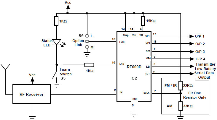
Fm Remote Encoder And Fm Decoder Using The Ics Rf600e And Rf600d

Low Power Mw Am Transmitter R Electronics

Fm Transmitter Fm Transmitters Electronics Circuit Electronic Engineering
Fm Basic Frequency Modulation Components Testing Of Fm Transmitter
Fm Basic Frequency Modulation Components Testing Of Fm Transmitter
Power Amplifier Design For Fm Transmitters With Working

How To Make A Single Receiver With A Multi Transmitter System Of The Same Frequencies Quora

Fm Transmitter Block Diagram And Explanation Of Each Block Pdf Block Diagram Fm Transmitters Diagram

Simple Am Transmitter With One Tetrode Vacuum Tube Electronics Forum Circuits Projects And Microcontrollers

A Dead Simple Well Constructed Fm Transmitter Hackaday

Booster Fm 25 Watt Electronics Circuit Basic Electronic Circuits Transmitter
A Dead Simple Well Constructed Fm Transmitter Hackaday
Fm Basic Frequency Modulation Components Testing Of Fm Transmitter

Fm Transmitter Long Range Fm Transmitter Simple Project Smart Tech Idea 2020 Fm Transmitters Electronic Circuit Projects Electronics Mini Projects